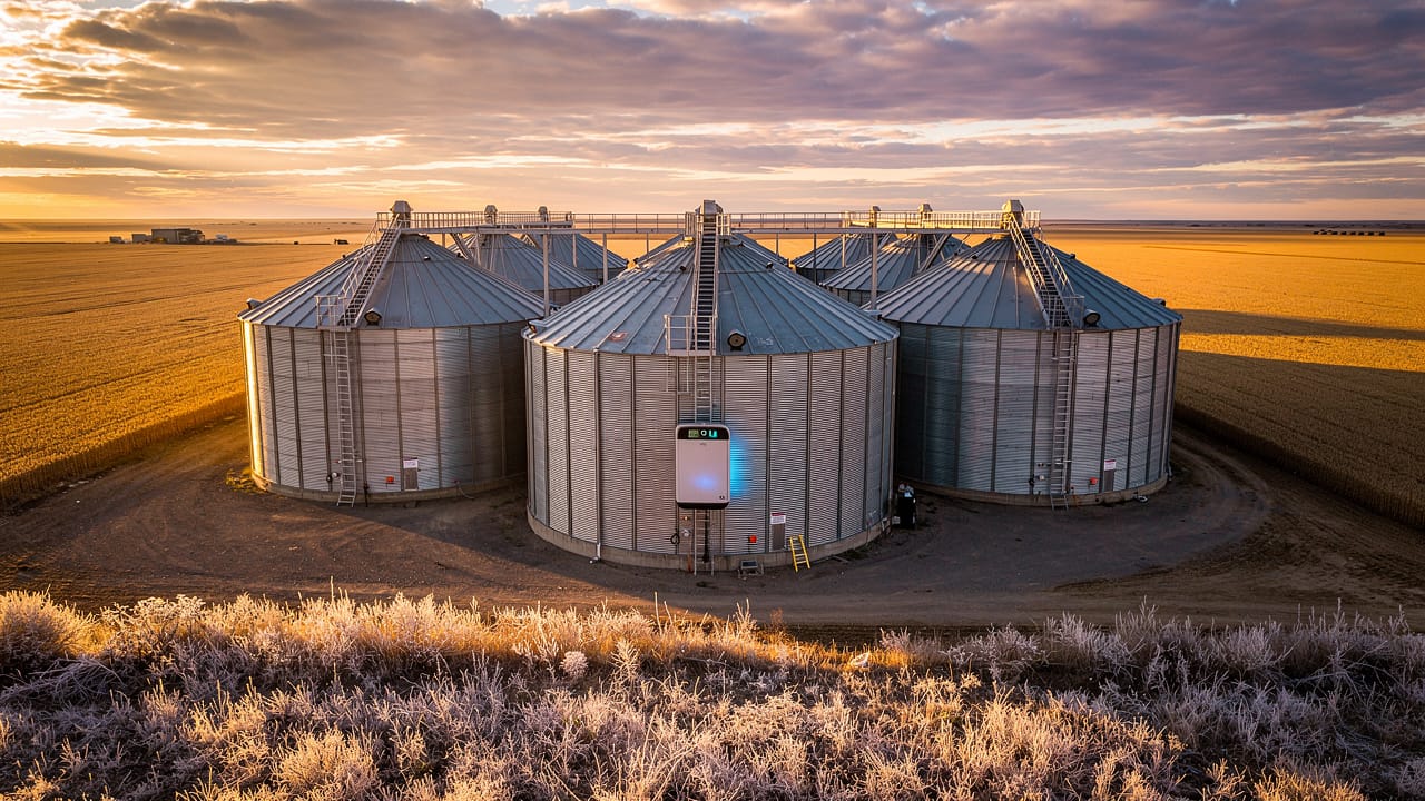
Farms run on power around the clock, and a weak electrical design shows up fast as dead livestock, spoiled grain, and blown equipment. In this guide, we explain how to design farm electrical systems that are safe, code compliant, and built for long-term operation. We walk through core design principles, demand load calculations, distribution layout, material choices, safety systems, and future-ready planning, based on the way we approach projects at Cove Electrical.
Introduction
When a ventilation fan quits in the middle of a hot summer night, the clock starts ticking. In a few hours, a barn can go from normal to deadly for livestock, all because of one weak link in the electrical system. For anyone asking how to design farm electrical systems that do not fail, that scenario sits at the center of the discussion.
Farm electrical work is not a scaled-up version of residential wiring. Conditions are harsh and unrelenting:
-
Moisture from washdowns and humidity
-
Corrosive gases from manure
-
Dust from feed and bedding
-
Rodents and insects
-
Pressure washing and chemical cleaners
-
Impacts from animals and machinery
Materials that survive just fine in a house can break down quickly in a hog barn or grain handling building, and that breakdown often shows up as heat, arcing, or fire.
On top of that, farms run many critical loads at once. Common examples include:
-
Ventilation fans and tunnel ventilation
-
Grain dryers and augers
-
Irrigation pumps
-
Heaters and heat lamps
-
Compressors and milk coolers
-
Controls, sensors, and automation
All of these depend on power that stays on and stays within the right voltage range. Designing this kind of system is not a DIY weekend project. It takes extensive electrical experience, strict code compliance, and a system mindset that looks at the whole operation, not just one panel.
At Cove Electrical, we build every farm system around four goals that never change. The system must be safe, adequate for real loads, efficient so it does not waste energy or damage equipment, and expandable so the farm can grow. In this article, we explain how we apply those goals—from load calculations and central distribution to material selection, grounding, and planning for future needs—so operators can make informed decisions and avoid costly mistakes.
Key Takeaways
-
Farm electrical design must follow the National Electrical Code (NEC), including Article 547 for agricultural buildings. Standard residential materials and methods do not survive moisture, gases, and dust in barns and grain facilities. Code compliance supports safety, insurance requirements, and long-term operation. Cutting corners here shows up later as equipment failures and fire risk.
-
Accurate demand load calculations for each building guide the size of services, feeders, and panels. They prevent overloaded circuits and surprise upgrade costs. A central distribution system with one main service and feeders to each building often offers the best mix of safety, flexibility, and cost control. Agricultural-grade, nonmetallic, moisture-resistant wiring, boxes, and panels are mandatory in livestock and washdown areas.
-
Grounding, bonding, and GFCI protection protect workers and animals from shock and stray voltage while also helping breakers trip fast during faults. Designing for expansion, backup power, automation, and future solar or wind from the start costs far less than rebuilding later. Cove Electrical focuses on systems for operations that cannot afford downtime, so these design choices are built into every farm project we take on.
The Foundation – Core Principles of Farm Electrical System Design
Every good farm electrical system starts with clear design rules. We rely on four core principles for every agricultural project we take on, and we align them with the National Electrical Code (NEC), especially Article 547 that covers agricultural buildings.
“Electrical installations in agricultural buildings shall be designed for the corrosive and damp conditions present.”
— Paraphrased from NFPA 70, National Electrical Code, Article 547
We organize our work around these four principles:
-
Safety
Barns and grain facilities operate in harsh conditions with moisture, ammonia, hydrogen sulfide, dust, and constant physical impact. Standard residential boxes, steel conduit, and open motors simply do not last there. We design with materials and methods rated for those conditions and treat code as the starting line, not the finish. -
Adequacy
A system that runs fine on day one but has no headroom for another fan, a larger grain dryer, or an added irrigation pivot turns into a problem quickly. We calculate real loads for lighting, ventilation, grain handling, pumps, and automation, then size services, feeders, and panels to handle both current and near-term growth. -
Efficiency
Long feeder runs, undersized conductors, and poor panel placement cause voltage drop that overheats motors and shortens equipment life. We place distribution where loads are centered and size conductors to keep voltage drop within recommended limits, which protects motors and helps control energy costs. -
Expandability
Farms change and grow. We design central distribution, spare breaker spaces, and oversize conduit paths so new buildings and systems can be added without tearing everything apart. At Cove Electrical, we follow these four principles because they support daily operation, not just passing inspection.
How to Calculate Electrical Demand Load for Farm Buildings
Demand load calculation is the starting point for every service size decision on a farm. It tells us how much current a building can draw under real operating conditions so we can choose the right service entrance equipment, feeder conductors, and main disconnects. The NEC, primarily Article 220 and Section 220.40, provides the method we follow, and USDA research into Energy Balance Model Development further illustrates how accurately accounting for all energy inputs and loads is critical to reliable agricultural facility design.
We use a step-by-step approach:
-
List all known and expected loads
We start by listing every permanently wired piece of equipment rated at 1,500 watts or 1 horsepower and higher, such as:-
Large fans
-
Milk coolers
-
Grain augers and conveyors
-
Water heaters
-
Compressors and pumps
We use the full-load amperage from the nameplate for each item. The largest motor on the list is then multiplied by 125% so the system can handle startup surge and occasional overload without repeated nuisance trips.
-
-
Add general-use loads
Next, we add the general-use loads that are easy to overlook. For each standard convenience outlet, we assign 1.5 amps at 120 volts. We use the same number for each lighting outlet. These values cover portable tools, pressure washers, and lights that may not be installed yet but usually appear once the building is in use. -
Convert and combine loads
After we have the full list, we convert the 120‑volt loads to their 240‑volt equivalent by dividing the amperage by two. This allows us to add every load on the same basis. We then sum all the loads to find the total connected demand for that building. -
Handle single-purpose equipment separately
Single-purpose equipment like a large irrigation pump or stand‑alone grain dryer is handled on its own and sized to its full-load rating rather than through the blended demand method above. These loads can dominate a service and deserve individual attention. -
Select the service size
With the total demand known, we select a service size that is equal to or above that number, using standard service ratings such as 60, 100, 150, 200, or 400 amps. Code requires at least 60 amps for most farm buildings, with 30 amps allowed only in small, single-load structures such as a remote well.
From experience at Cove Electrical, underestimating demand is one of the fastest ways to lock a farm into costly upgrades just a few years later. A careful calculation up front saves time, money, and frustration down the road.
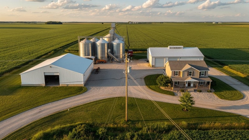
Designing a Centralized Farm Distribution System
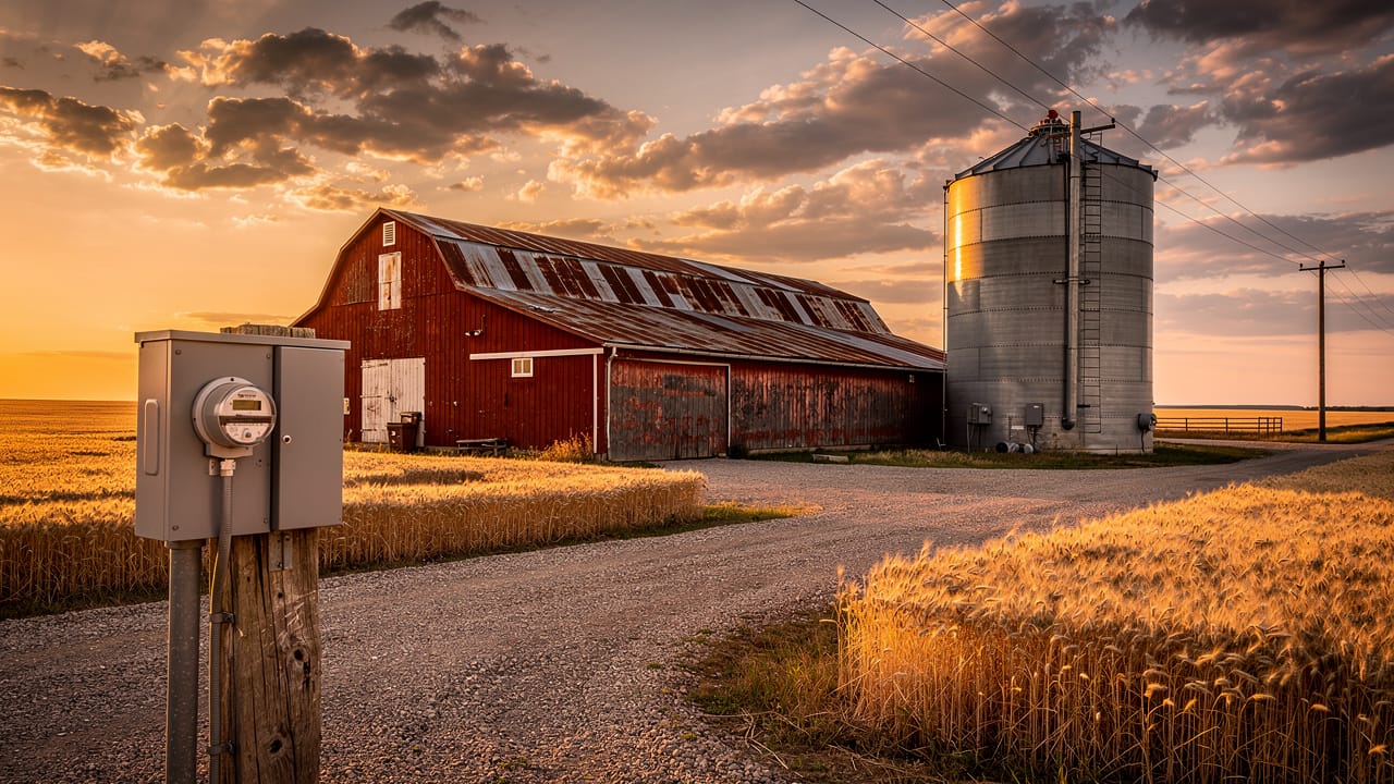
Once we understand the loads in each building, the next step is deciding how to feed them. For multi‑building farmsteads, we almost always recommend a centralized distribution system. In this setup, one main service and meter sit at a central point, and individual feeders run from that point to each barn, shop, grain system, or pump.
The main distribution equipment usually has up to six breakers or fused switches. One of these acts as a main disconnect for the entire farm and is often arranged so it can work with a manual or automatic transfer switch for a standby generator. This spot becomes the control center for power on the property.
A central distribution layout brings several key advantages:
-
Fault isolation
If a short or fire affects one barn, the breaker on that feeder trips, but the rest of the farm stays live. Critical loads such as water wells or backup ventilation lines can be fed from dedicated breakers that stay on when other parts are shut down. That separation supports both safety and uptime. -
Straightforward expansion
When a new building goes up or a grain system grows, we run a new feeder from the main pole or pad. The existing feeders and services do not need to be rebuilt, which keeps project cost and downtime under control. -
Material and labor savings
When we place the main service near the electrical load center of the farm, the total length of heavy feeder wire across all buildings is usually lower than it would be with separate, scattered services.
We size the main farm service using NEC diversity factors: 100% of the largest building load, 75% of the second, 65% of the third, and 50% of the rest — an approach consistent with findings on System Optimization and Primary distribution design in agricultural energy systems. That reflects the reality that not every building runs at full load at the same time. We always coordinate final service location and layout with the power supplier, since access, clearances, and utility standards all matter. At Cove Electrical, this central model is our standard because it matches the way real farms operate.
Choosing the Right Materials for Agricultural Environments
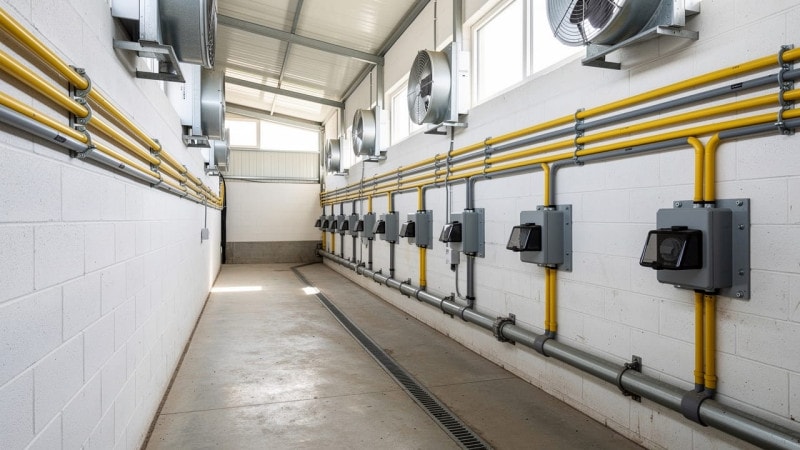
Material choice on a farm is not just a durability question; it is a safety and compliance issue. Moisture from washdowns, corrosive gases from manure, dust from feed and bedding, and physical abuse from animals and equipment all attack electrical parts. Residential‑grade wiring, boxes, and fixtures fail quickly under that stress.
For wiring and conduit, we keep everything surface‑mounted so it can be inspected and so moisture does not get trapped in walls. Common practices include:
-
Using moisture-resistant type UF cable, fastened with plastic‑coated staples at close, regular spacing
-
Using rigid Schedule 40 PVC conduit with individual moisture‑rated conductors where we expect impact or heavy wear
-
Sealing conduit runs where they pass between warm and cold areas to reduce condensation
-
Using flexible nonmetallic liquidtight conduit for short connections to fans and similar equipment so vibration does not damage fixed wiring
Standard type NM residential cable (often called Romex) is not allowed in these agricultural spaces, and we do not install it there under any condition.
Boxes and receptacles also need special care:
-
We use molded nonmetallic boxes because metal boxes corrode fast in barns.
-
Every box gets a gasketed cover so dust and moisture stay out.
-
Receptacles use spring‑loaded weatherproof covers that close when nothing is plugged in.
-
We route conduit and cable into boxes from the side or bottom so wash water and condensation do not run straight in.
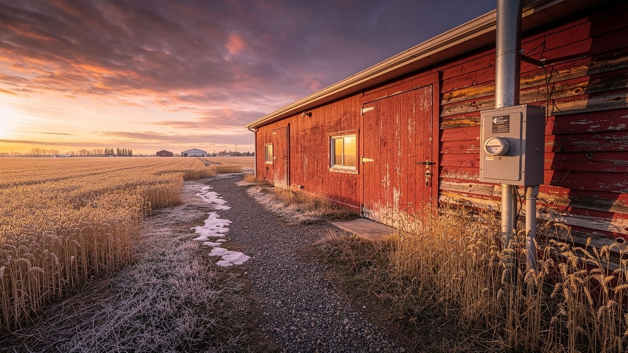
Distribution panels are kept out of corrosive areas whenever possible, such as in an office or equipment room, inside an outdoor‑rated enclosure. When a panel must be in the animal area, we specify nonmetallic moisture‑tight enclosures that are rated for washdown. We surface‑mount panels on fire‑resistant backing with a small air gap to reduce heat and condensation build‑up. These choices raise initial material cost a bit, but they pay back in fewer failures, safer barns, and less downtime.
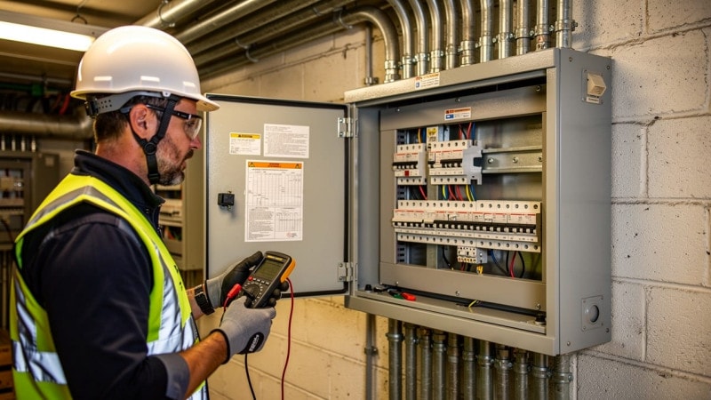
Critical Safety Systems – Grounding, Bonding, and Circuit Protection
Even with the right layout and materials, a farm system is not safe without proper grounding, bonding, and circuit protection. These elements protect both people and animals from shock, stray voltage, and fire.
“Grounding and bonding provide a low‑impedance path for fault current, helping overcurrent devices operate properly.”
— Paraphrased from NFPA 70, National Electrical Code
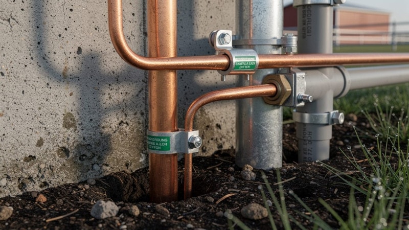
System grounding begins at the main service disconnect. There, the neutral conductor is tied to a grounding electrode, often an 8‑foot copper‑clad rod driven into the soil. This connection stabilizes system voltage and gives lightning and utility‑side faults a safe path to earth. The grounding conductor must be continuous and protected where it runs.
Equipment grounding runs alongside every circuit. We bond the metal frames of motors, panels, boxes, and other equipment back to the grounding bus in the panel with a bare or green insulated conductor. If a hot wire ever touches that metal, the fault current follows the low‑resistance ground path, trips the breaker quickly, and shuts the circuit off. Without this path, that same fault can leave what looks like a normal motor frame sitting at line voltage.
Equipotential bonding is especially important around livestock. Code requires that all metal work an animal could touch within 8 feet of the floor be tied together and back to the grounding system. That includes water lines, gates, stanchions, pen hardware, and any mesh in the floor slab. When everything is bonded, there are no small but harmful voltage differences between a cow’s feet and a water cup, which helps avoid stray voltage issues that reduce intake and stress animals.
On top of grounding and bonding, we rely on ground-fault circuit interrupters (GFCIs) in all wet, damp, or washdown locations. GFCIs sense very small differences between outgoing and return current and cut power in a fraction of a second, which sharply reduces shock risk when water is present. Finally, every branch circuit is protected by a correctly sized breaker or fuse, and continuous loads such as fans and heaters are kept within 80% of that rating. At Cove Electrical, many of the worst field problems we see trace back to skipped grounding or bonding steps, not the visible cables and panels.
Future-Proofing Your Farm Electrical System
Farm operations rarely stay the same for long. New barns, bigger grain systems, more automation, and on‑site generation all put new demands on electrical infrastructure. We plan for that from the start so operators are not forced into expensive rebuilds.
One of the simplest steps is oversizing main panels and conduit runs slightly beyond current calculated demand. Adding a few extra breaker spaces and running a slightly larger conduit during the first build costs little compared to digging up feeders or swapping a main panel later. We also design central distribution points with room for added feeders to future buildings.
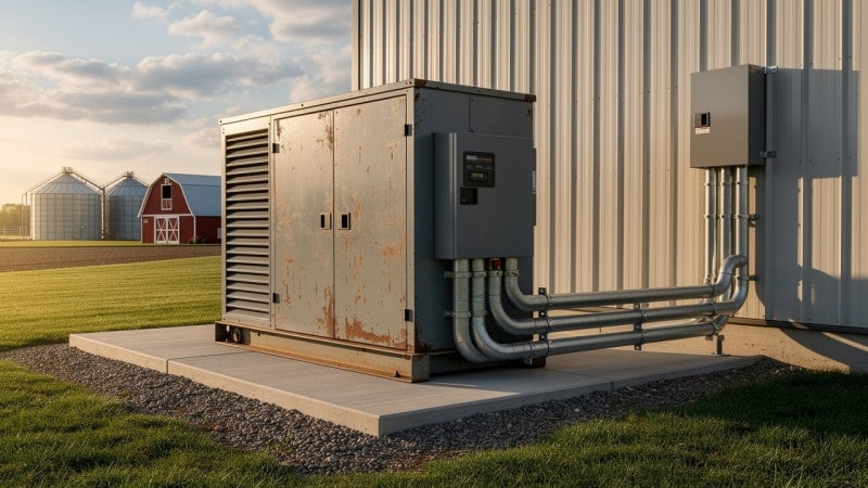
Backup power is another major piece. For livestock ventilation, irrigation pumps, grain dryers, and control systems, a long outage is not acceptable. We integrate standby generators and proper transfer switches into the main distribution so that critical circuits can keep running when the utility fails. Because Cove Electrical focuses on operations that depend on constant power, generator planning is part of our standard farm design process.
We also think ahead about automation, monitoring, and renewable energy. That means leaving panel capacity and conduit paths for future control panels, sensors, and communication lines. When a farm later chooses to add solar or wind, a system that was built ready for it can accept a grid‑tied array with far less rework. Planning these items early supports long‑term stability and better return on the electrical investment.
Conclusion
Designing a farm electrical system the right way means more than hanging a few panels and pulling wire. It starts with safety and code compliance, then moves through accurate load calculations, a central distribution layout, the right agricultural‑grade materials, solid grounding and bonding, and room to grow.
On a farm, electrical failures are not small annoyances. They are lost production, stressed or dead livestock, ruined grain, and sometimes full building fires. That is why at Cove Electrical we focus on systems for operations that cannot afford downtime and why our designs put reliability ahead of shortcuts.
If a new farmstead is being built, an older system is due for an upgrade, or automation and backup power are under consideration, we are ready to help. Reach out to Cove Electrical to discuss the operation, walk through loads and risks, and design an electrical system that supports the work every single day.
FAQs
Question 1 – What Electrical Code Applies to Farm Buildings in the US?
The National Electrical Code (NEC) includes a dedicated section for agricultural buildings called Article 547. It covers requirements for moisture‑resistant wiring methods, corrosion‑resistant components, and special grounding and bonding rules for livestock areas. Local authorities may add their own amendments, so final designs must match the version of the code adopted in that state or county.
Question 2 – What Is the Minimum Electrical Service Size for a Farm Building?
For most farm buildings, the NEC calls for a minimum service of 60 amps. A 30‑amp service may be allowed for very small, single‑load structures such as a lone well pump. In practice, the real service size should always come from a full demand load calculation rather than just picking the minimum.
Question 3 – Why Can’t I Use Standard Residential Wiring (Romex) in a Barn or Livestock Facility?
Type NM cable, often called Romex, is made for dry residential spaces, not for barns. It does not stand up to moisture, corrosive gases, dust, and physical abuse found in agricultural buildings. It can break down quickly, which raises fire risk and creates clear code violations. Article 547 calls for moisture‑resistant cable such as type UF or individual conductors in Schedule 40 PVC conduit instead.
Question 4 – How Do I Prevent Stray Voltage from Affecting My Livestock?
Stray voltage happens when there are small voltage differences between metal surfaces animals can touch, such as floors and waterers. To control this:
-
All metallic items within animal reach are bonded together and tied into the grounding system, creating an equipotential plane so no difference exists.
-
Proper system and equipment grounding are the base requirement.
-
A qualified electrician should inspect and test the system if stray voltage is suspected.
Managing grounding and bonding correctly is one of the most effective ways to protect livestock health and behavior.